Wohmart.COM
SY99 MMB Installation & Usage (v1.1)
Upgrade, install, load samples, make music. Soldering is required.
READ THIS FIRST
New: If you have the newer v1.2 expansion board, use these instructions instead.
 Installation of the SY99 Magic Memory Board (MMB) requires soldering 2 wires directly to the pins of a surface mount IC on the Yamaha SY99. These pins are just 0.4 mm (0.015") wide, and are spaced just 1.27 mm (0.05") apart. By contrast, traditional through-hole ICs have pin widths of ~1.5mm (0.06"), and are spaced 2.54mm (0.1") apart.
You will need:
- a soldering iron with a fine point, suitable for SMT work
- good wire strippers
- solder (63/37 is recommended)
- solder-wick in case of mistakes
- a magnifying glass
- an anti-static strap/static-free workspace
- a continuity tester with fine-pitch probes
- …and steady hands to do a good job.
If you doubt your ability to install this modification yourself, contact your local musical instrument store and ask for a recommendation for a nearby synthesizer technician. They should be able to install this modification quickly and at low cost.
Neither WohMart.COM nor Just Some Enterprises Inc. are responsible for any damage you may cause your SY99 by installing the Magic Memory Board upgrade. Perform this upgrade at your own risk. If you have any questions during the installation process, please write to us at support@wohmart.com.
Step 0: Check your kit
Unpack your MMB kit. It should contain the following:
- The 8MB Magic Memory Board itself, with the purple-wire 14-pin jumper cable already attached,
- a CR2450 coin cell battery,
- an OS EPROM, preloaded with version 1.60,
- (optional) a new CPU, preloaded with version 1.57 of the CPU ROM (required if your SY99's OS revision is < version 1.57,
- (optional) a PLCC extractor, for removing the old CPU from its socket.
Step 1: Upgrading your OS to v1.60
First, let's upgrade your operating system.
On a workspace large enough to hold the SY99, place a soft cloth, towel, or blanket. This will prevent the front of your SY99 from getting any scratches.
Unplug all cables and AC power from your Yamaha SY99. Place the SY99 upside down on your prepared surface. Then, with a #2 Philips screwdriver, remove the 24 screws holding the bottom cover onto the machine:
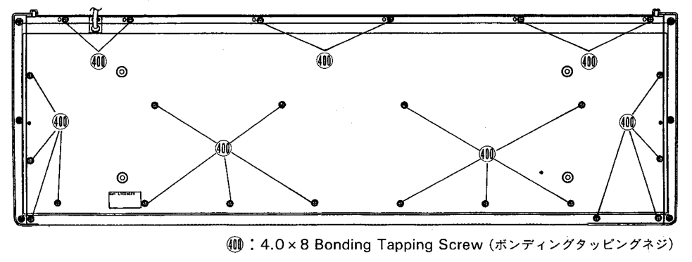
Put the screws and cover somewhere safe, where you won't lose them.
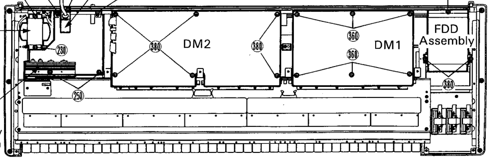
Inside of the SY99, you will see the power supply assembly to one side, and the floppy disk drive (FDD) assembly with mod/pitch wheels on the other. For the rest of this walkthrough, keep the power supply on your left and the FDD assembly on your right, as in this diagram:
DO NOT TOUCH ANY OF THE EXPOSED POWER SUPPLY ASSEMBLY. The capacitors in this section can hold a high charge a long time, even after the SY99 has been unplugged. Stay safe!
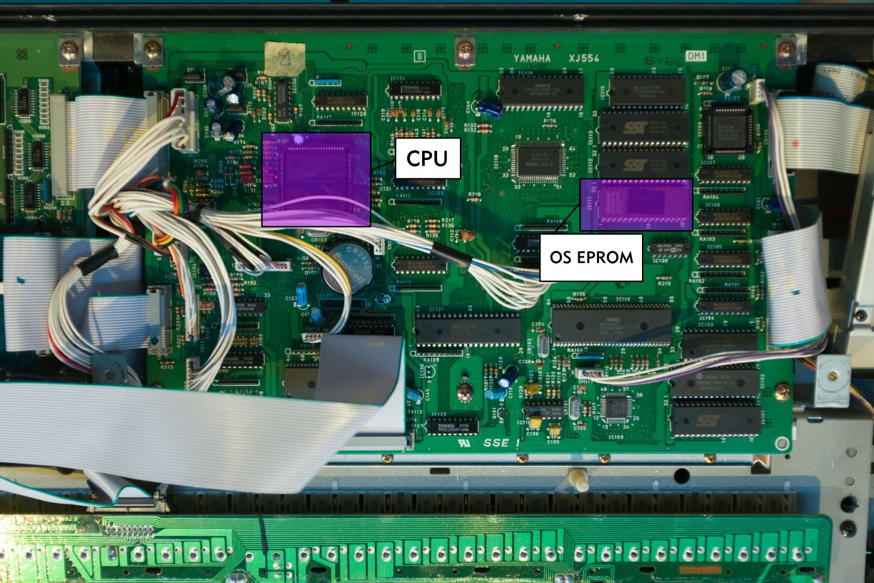
Next, remove the main OS EPROM. This chip is on the DM1 board to the right, and is labelled IC111:
NOTE: If your SY99 is one of the later models, IC111 will not be socketed; you will need to desolder IC111. If this is the case, remove all connectors on the DM1 board (see diagram above), being sure to note which connector plugs in where. (We recommend writing the connector number from the DM1 board on the side of the disconnected connector, with a mechanical pencil.) Then, unscrew the 6 screws labelled 360 in the above diagram and lift DM1 out of the SY99. To desolder IC111, we wholeheartedly recommend using the DEN-ON SC7000Z Portable Desoldering Gun, but other desoldering tools can be made to work as well. Once the old EPROM is desoldered, solder into place the IC socket supplied with your MMB kit. Finally, reinstall DM1 into the SY99.
Otherwise, using an IC extractor, remove IC111 from its socket. If you do not have an IC extractor, use a small slotted screwdriver to pry up one end of the chip, then the other. Go back and forth, being sure not to pry too far on any one side at a time. Do not damage the PCB while you do this!
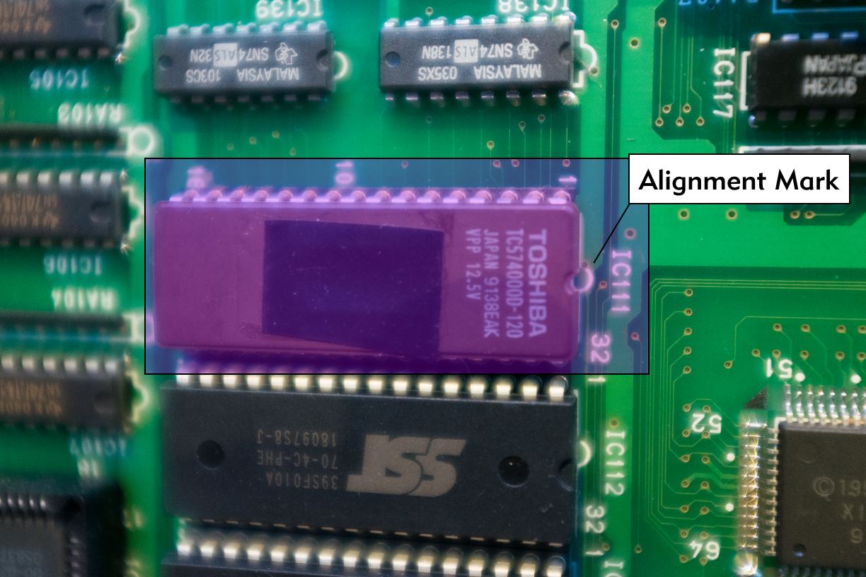
Then, install the new EPROM into the socket, being sure you use the correct orientation. The "notch" on the top of the IC should match the silkscreened "notch" on the DM1 circuit board, as shown below:
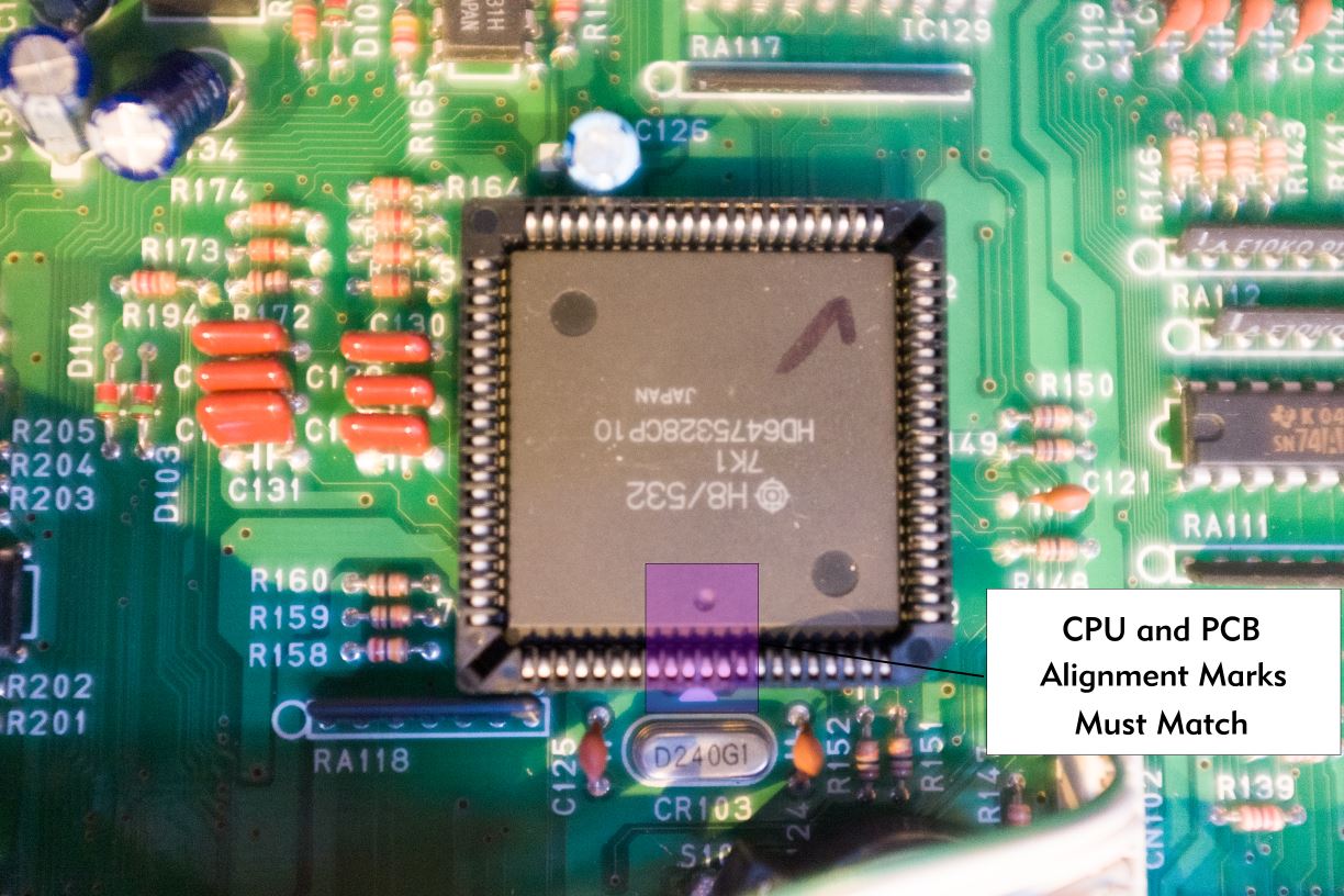
If you purchased the CPU upgrade (required if your SY99's OS is <1.57), swap the CPU now. The CPU is a large, square IC in the top middle of DM1, just above the backup battery. Using a PLCC extractor, insert the two prongs of the extractor into the cut-outs in the CPU socket, and pry the CPU out of the socket gently. Using a screwdriver instead of the PLCC extractor WILL DESTROY THE SOCKET!
Install the new CPU into the socket, being sure you use the correct orientation. The dot in the center of one side of the CPU should line up with the white arrow silkscreened on the DM1 board, as shown below. Press evenly and firmly with two thumbs.
Last step - place the supplied sticker over the battery and its holder. This is critical - if the battery or its holder contact the bottom cover, the battery will be shorted out and drain immediately.
Now, place the bottom cover back onto the SY99 and attach it using at least 4 of the original screws. Flip the SY99 back over, plug in the power cord, and turn it on. If you do not see the SY99 booting up immediately, turn the SY99 back off, re-remove the bottom cover, and check your work.
The boot screen should show "YAMAHA SY99 Expanded 8MB RAM" and the WohMart.COM notice. Double-check that the OS upgrade is complete: while pressing the [Voice] switch, press and hold the [INTERNAL] Memory switch, then the Patch [1 (OP 1)] switch. The version of the MAIN ROM should be displayed as 1.60. Press [EXIT] to return to the main screen.
At this point, a full factory reset is strongly recommended. It is required if you are upgrading from < v1.57. To perform the reset, while pressing the [Voice] switch, press and hold the Bank [D/EL4] switch, and the Patch [8] switch. At the SY99 TEST screen, press the [COPY] button to complete the factory reset process.
Congratulations! You've upgraded your SY99's OS. In preparation for the next step, turn off your SY99, unplug it, flip it upside down, and remove the bottom cover again.
Step 2: Installing the MMB
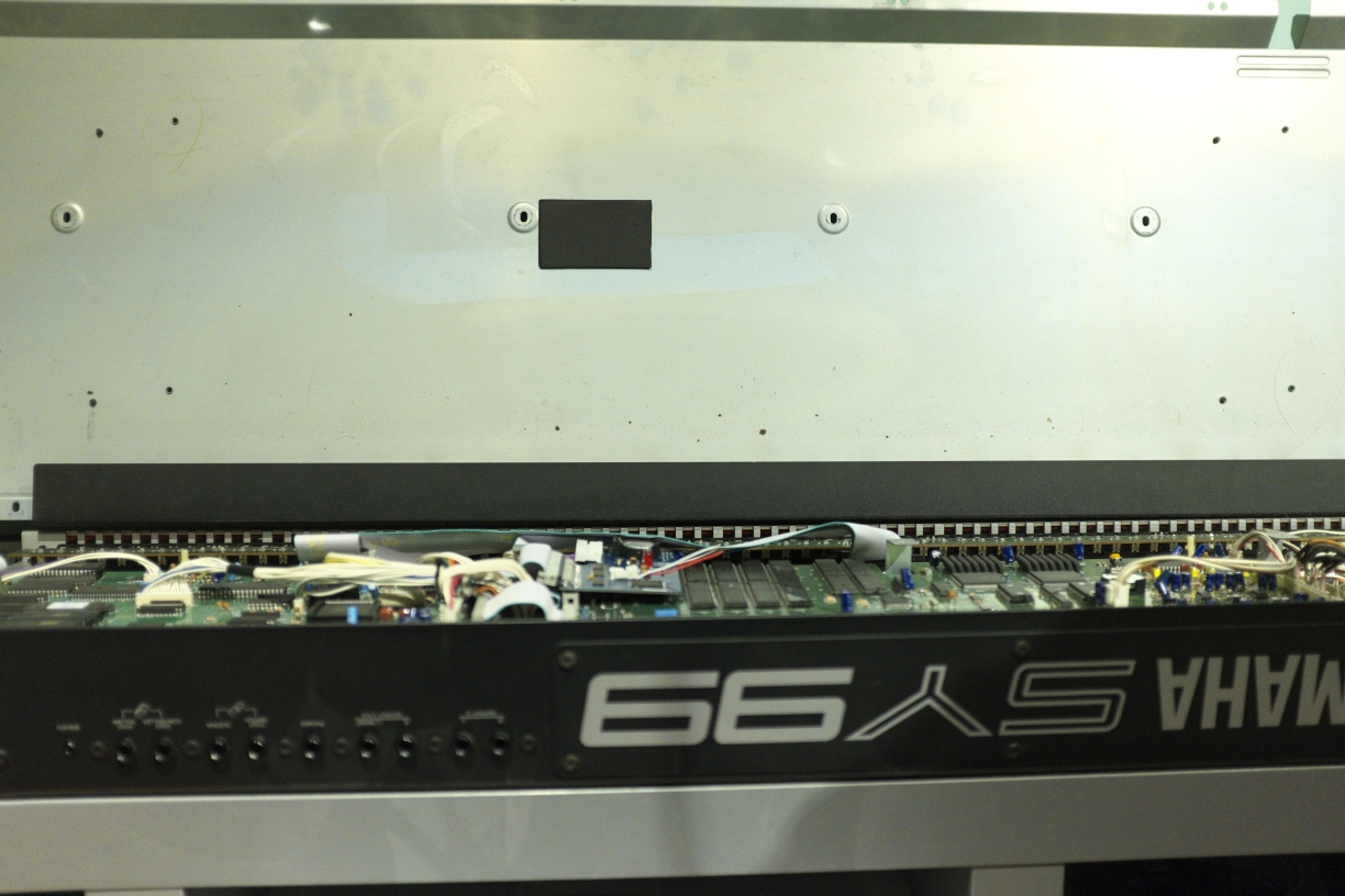
Now let's install the Magic Memory Board itself. Looking at the bottom center of your opened SY99, on the right edge of the DM2 board, identify the 40-pin connector CN208 and the 14-pin connector CN209:
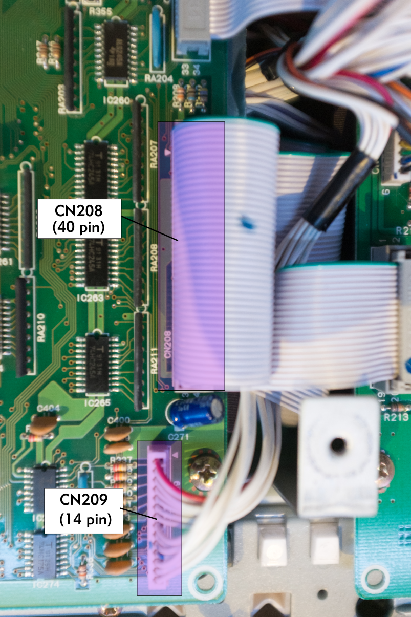
Remove the cables from these two connectors. The 14-pin cable that used to connect to CN209 will remain unplugged after installing the MMB. You can tuck this connector underneath the large L-shaped bracket between DM2 and DM1.
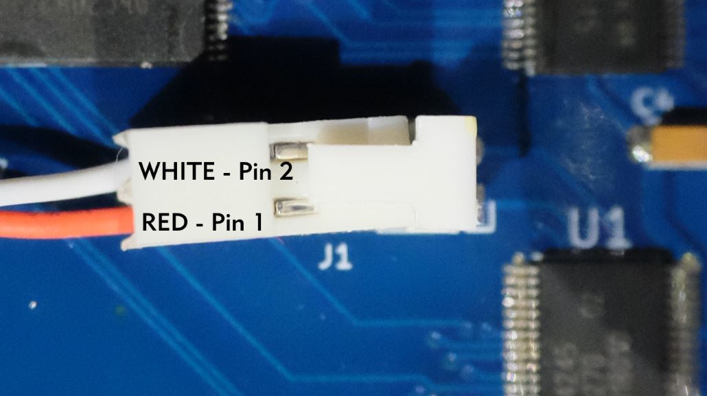
It's time to do that difficult soldering work mentioned above. Take the MMB-supplied 2-wire jumper and strip 2mm (~0.1") of insulation off the end of each wire. Identify IC271 at the bottom right of the DM2 board. Tin the stripped wire leads, then solder the red wire to pin 1 and the white wire to pin 2 of IC271, like this:
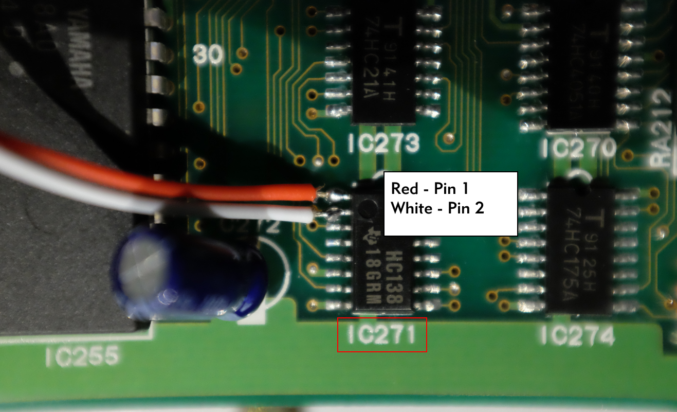
Use a continuity meter to ensure you did not short pin 1 to pin 2, or pin 2 to pin 3. This is very easy to do by accident!
There is a capacitor between IC271 and IC275; bend this capacitor away from IC271 so it rests against IC275, as in the picture above. The MMB will rest against this capacitor.
Time to install the MMB!
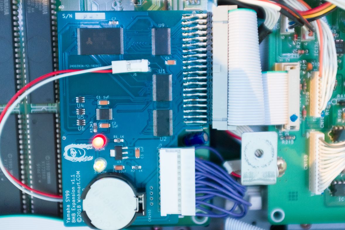
- Remove the MMB from its protective packaging. Hold the MMB by its edges only.
- Hold the board with the components and J1 facing you. If you see the shruggy artwork, you're holding it upside down! ☻
- Install the supplied CR2450 coin cell battery. The battery's positive (+) terminal faces up (towards you).
- Connect the 14-wire cable hanging off of the MMB to the 14-pin CN209 connector. Be very very gentle with this connector, it is fragile!
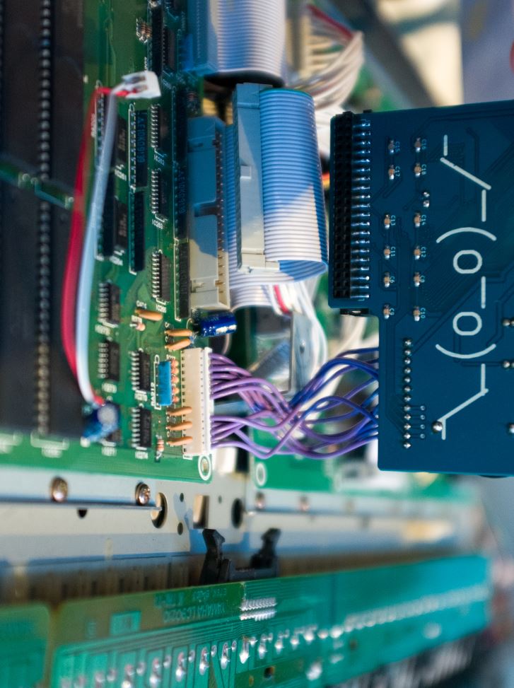
- Holding the 2-wire jumper cable out of the way, install the MMB into 40-pin connector CN208 on DM2, ensuring you install the board with the correct orientation. The board should hang over DM2 and IC271, not over DM1. The "key" on the MMB's 40-pin connector should ensure the pins align correctly, but double-check that the connector is not off by an entire row of pins accidentally. The key on the connector should ensure this. The board should insert into CN208 easily; if you feel any resistance, remove the board from CN208 and try again.
- Connect the 2-wire jumper cable to jack J1 on the top of the MMB. Be sure the red wire is on the lower pin. The jack and plug are keyed to make insertion easier in one direction - that's the right way.
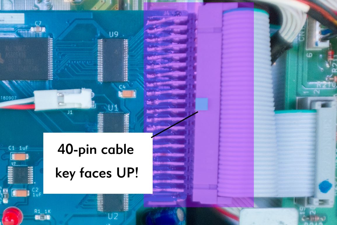
- Connect the 40-pin cable that used to connect to CM208 to the MMB. The "key" on the cable (see picture below) should face up, towards, you. (This cable runs to the Waveform and Data card slots on the front of the SY99. If you forget to install it, those slots will not work!)
- To prevent the battery from discharging through the case, apply the included piece of foam tape to the inside of the bottom cover. The tape should go next to the hole for the screw that attaches right next to the MMB, in line with it, per the picture below. The position isn't critical; the goal is to prevent the battery from touching the metal of the bottom cover once it is reattached.
Step 3: Testing the MMB
BE VERY CAREFUL IN THIS NEXT SECTION. Do not touch the inside of the SY99 while the AC power cord is connected.
With the bottom cover still off of the SY99, connect the AC power cord to an AC socket. Being very, very careful not to touch the inside of the power supply, turn on the SY99. Immediately, the two LEDs on the MMB should light up, red and green. Turn off and disconnect the SY99 from the AC power source.
If the LEDs did not light up, go back to the previous section and make sure the MMB is installed correctly into the 40-pin CN208 connector. Odds are you installed the board off by one row of pins.
Optional: At this point, if you want to make the installation semi-permanent, you can apply some hot glue to the CN208 connector, being sure to get some on the underside of the MMB as well. This will hold the board in place more securely. If necessary, the glue can be removed with a hobby knife or blade, allowing you to remove the MMB.
Replace the bottom cover onto the SY99 and attach it with the original 24 Philips screws. Then, flip your SY99 right-side up.
Plug your SY99 into an AC outlet and turn it on. After boot, press the [SYSTEM] button, then the [F1] button.
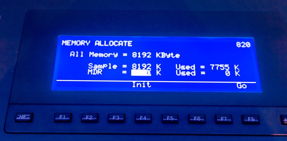
Select option 06: Memory Allocate with the wheel or keypad, and press [ENTER]. The SY99 displays the Memory Allocation screen (page 820).
Press [F4] to initialize the memory. Read the warning, and when ready, press [+1/YES]. After a few seconds, initialization completes. The Memory Allocation screen should show All Memory = 8192 KByte.
Congratulations, you've finished upgrading your SY99!
Step 4: Using the 8MB of expanded sample RAM
This section is preliminary, and may be updated soon based on info provided by the Yamaha SY99 community.
There are 4 ways to load sample data into a Yamaha SY99:
- Via data copy from a Waveform Data Card inserted into the slot on the front of the SY99. This is the fastest way to copy data.
- Via an "All Data"
.T##file from the floppy drive (or USB emulator). These files include patches, "Waveforms" (which is SY99-speak for a collection of samples), and all of the samples used in each Waveform. - Individual samples can also be loaded from the floppy drive (or USB emulator) in Yamaha "Wave" format. These
.W##file formats are TX16W-compatible sample files. - Individual samples can be loaded by the MIDI Sample Dump standard. This is the least-recommended approach, since MIDI transfer rates are slower than the other three options.
1. Waveform Data Card: Yamaha originals, plus the WaveBlade
If you want the fastest transfer possible, purchase the Sector101 WaveBlade 8MB Waveform Card & Programmer. Follow the instructions Sector101 provides to load your waveforms off of your computer into the WaveBlade Waveform Card. Use of the sy.factory synthesizer librarian software can make loading your WaveBlade with your own samples easier. Insert the card into your SY99, then use the [Utility] menu, [F3] Card page, and 04: Load from Wave Card option to copy the data from your WaveBlade into the SRAM. This takes about 30 seconds per 2MB bank.
The advantage of this approach is that you can have a total of 16MB of waveform data available: 8MB loaded into your SY99's SRAM, plus the 8MB (in 4 2MB banks) on your WaveBlade card. If you buy more than one WaveBlade, this is the fastest way to switch waveform sets on the fly, and would be great in a live performance setting.
The disadvantage to this approach is that you cannot store a full 8MB of waveform data in a single block on the WaveBlade. You must structure your data as 4 2MB blocks, meaning no single patch can access more than 2MB of sample data at a time. You also cannot exceed 99 samples stored in the SY99 at any given time - so be careful the total number of samples across all 4 banks does not exceed this number. Finally, the SY99 treats the Waveform Card as read only, meaning you cannot write modified waveform data or patches back to the card directly.
However, once your sample data is copied into the SY99, you can start making new patches that use >2MB of sample data each, and save those to floppy disk.
2. and 3. Floppy Disk Drive: FlashFloppy/HxC emulation and sy.factory
Another great way to transfer samples to and from the SY99 is via the floppy disk drive, the way Yamaha originally intended.
Due to the age of these drives, it is recommended to replace them with an emulated drive. These Gotek-branded devices cost around USD$40 and directly replace the original floppy disk drive. A small adapter is required to connect the SY99's floppy cable to these emulators. After installation, a USB pen/thumb drive slot allows you to access gigabytes of samples at a time, and makes for easy transfer from your USB-equipped computer. An LED or OLED display on the emulator, combined with two buttons to select the file, make changing virtual floppies a breeze.
You can create the disk files to place on a (real or emulated) floppy disk set using the sy.factory synthesizer librarian software. sy.factory will write out a multi-disk .T## set. The HxCFloppyEmulator program (linked below) can then place each of these files onto its own virtual floppy disk for loading into the SY99.
When loading a multi-disk set into the SY99, the display will not prompt correctly for disks numbered higher than 9. If you are loading a 10, 11 or 12 disk set, be sure to keep track of which disk you are on.
If you are interested in upgrading to an emulated drive, here are some useful links:
- AMIGAstore.eu. This store has the Gotek drive emulators, in both LED and OLED versions. These are known good to work with the SY99, as long as you select the FlashFloppy firmware. No extra cables are required.
- eBay listing for floppy cable adapter required to connect a Gotek drive to your SY99.
- FlashFloppy support page. This upgraded firmware offers a better experience when using a Gotek emulator, and is highly recommended. It uses the standard
.HFEvirtual floppy disk image file format. The SY99 is compatible with all versions of FlashFloppy. - HxC support page. This older firmware runs on the Gotek hardware and also supports the SY99. Download the
HxCFloppyEmulator_soft.zipfile from here to read/write virtual floppy images using your Mac or PC for either the HxC or FlashFloppy firmware. When setting the floppy format, be sure to select3"5 720KB DSDD FAT12as the floppy type. - If you're looking for a better price for a Gotek emulator, AliExpress offers a number of retailers with the drive, for as little as US$14. You will have to load the FlashFloppy firmware onto these drives yourself.
4. MIDI Sample Dump
The SY99 will accept individual samples via SDS, the Standard MIDI Sample Dump protocol. You can then assemble these into Waveforms using the SY99 front panel, and use those Waveforms in your own Patches. Store them in the battery-backed SY99, or backup to floppy disk when you're ready.
A known good utility for SDS from your Mac or PC to the SY99 is the Elektron C6 SysEx Manager. This is downloadable from the Elektron Analog Drive support page. The C6 utility also allows you to dump samples back out from the SY99 onto .SYX MIDI SysEx files if desired.
Recent posts suggests that MIDI buffering may be problematic in Windows 8 and 10; you may need to experiment with these settings.